Save a copy of the dxf as an R12 dxf, OpenSCAD likes it better. Straight lines may also have a problem, but there is not much of a reason to make straight lines out of many straight lines.Įach part of the logo with it’s own color for clarity. How do you know if you have three spline points along a line? Well, for the most common case in grid-drawn splines, it is when the x or y coordinate does not change for three points in a row (ie a spline with points:, the y-coordinate does not change).

If you have three spline points along a line, OpenSCAD will not like it, so you will have to alter your spline slightly by skipping the middle of the three points. Pay attention to the cursor information in the lower left of the window. Set your snap to endpoints (Snap -> Endpoints) and start drawing a spline (Draw -> Spline -> Spline). Now, highlight the old layer, you should see the points used to create the splines. However you do it, keep it clear and this will be much easier.

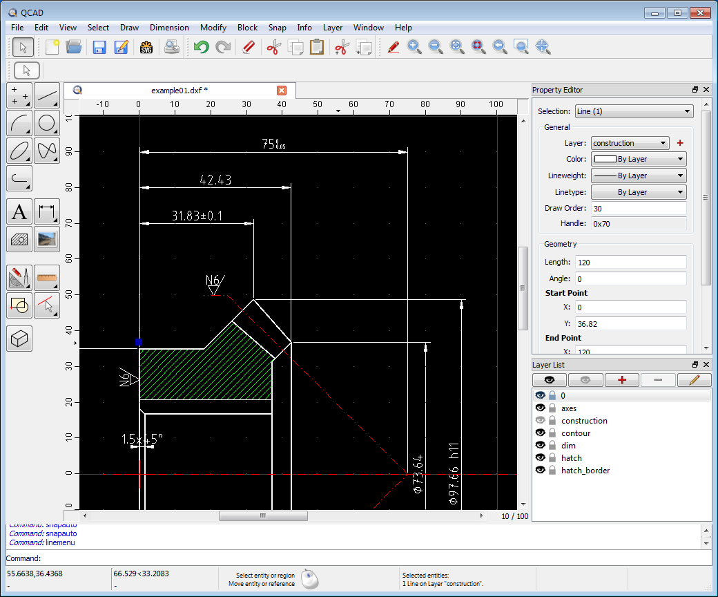
Name the new one new_foo or rename the old one to old_foo. Make a new layer to replace the old layer. Turn off all layers except for the one you want to touch up. If you find this next part too complicated now, you can skip ahead, but when you go to “Compile and Render” in OpenSCAD, and it reads that your object is not simple, you will not be able export an STL because you get the error “Object isn’t a single polyhedron or otherwise invalid! Modify your design.” you will have to come back to here to fix your splines. Plus, in this case, the wrenches won’t even touch the skull. Besides separate layers for separate parts, we are going to need to make sure there are no three spline points in a row as OpenSCAD will not be able to give you an stl. We had a layer for skull outline, face features, and a layer for each of the wrenches. You are going to need to have separate layers for the separate parts. This is nice and pretty and all, but it is not quite going to work with OpenSCAD. Here, try our logo (R12-type dxf) so you can follow along. Now, grab a dxf of a logo of your choice. To start with, you will need a 2D cad program, we used QCad. This how-to will walk through the process of creating a badge from a dxf file for a logo.
#Qcad printing no scaling how to
We figured we put you through enough posts about our CES badges without telling you how we did it or how to get one.


 0 kommentar(er)
